Yagi Antenna Projects and Information
Resources for building Yagi-Uda antennas, including designs and construction plans for various bands.
Yagi antennas are a popular choice for hams seeking directional gain, especially on VHF, UHF, and the higher HF bands. Their design allows operators to focus RF energy in a specific direction, improving signal strength for DX contacts and reducing interference from other stations. Many hams enjoy building their own Yagis, experimenting with element spacing and boom length to optimize performance for specific frequency ranges.
This category offers a wealth of resources for Yagi antenna projects, from simple portable designs for fox hunting to complex multi-element arrays for serious contest operation. You'll find detailed plans for single-band Yagis, including 6-meter designs like the EF0610, and multi-band options such as the DK7ZB triband VHF Yagi. There are also articles explaining Yagi-Uda antenna theory and construction techniques, helping hams understand how to achieve maximum gain and front-to-back ratio for their homebrew antennas.
-
 DF9CY - 10 Element for 432 MHz Winkler Antennen
 -
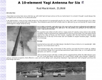
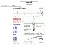
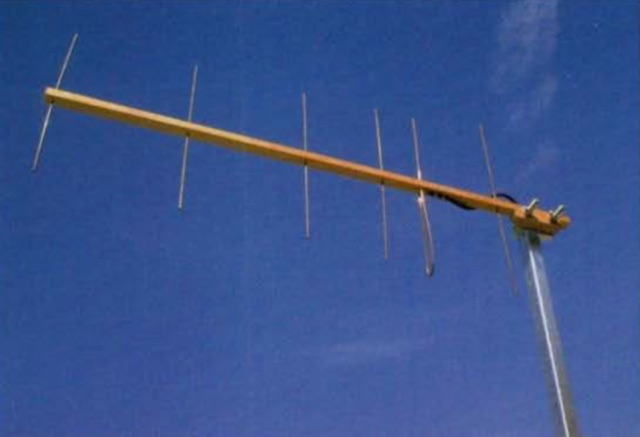
 A homemade 10 element Yagi Beam Antenna for 50 Mhz by Rod Mackintosh, a NBS Yagi on a 13.2 metre boom.
 -
 DJ9BV yagi antenna for 2 meters band
 -
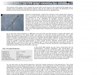 A 14 elemets yagi antenna for 432 MHz based on DK7ZB design
 -
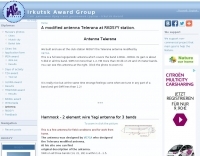 Hammock 2 element wire Yagi antenna for 3 bands 20-15-10 based on VE7CA project
 -
 A wire yagi antenna for 20 and 40 meters band suitable for outdoor and field day operations
 -
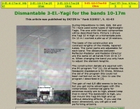
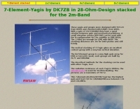
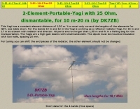
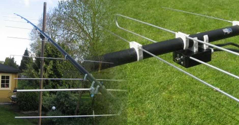
 2-Element parasitic Yagis for the Shortwave-Bands 10-12-15-17-20-30m. The antennas are feeded with the DK7ZB-match. A quarter-wave choke of coax is grounded at the socket.
 -
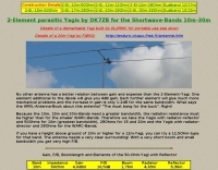 2-Element parasitic Yagis for the Shortwave-Bands 10m-30m
 -
 The KJ5VW 20 Meter Mini Yagi by Gary R. Hanson, Austin, Texas
 -
 20m 2-element light-weight Yagi antenna
 -
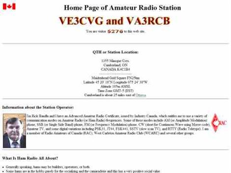 VE3CVG 222 MHz (1.25m) 6 element plumber's delight yagi antenna
 -
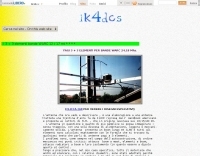
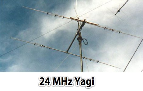
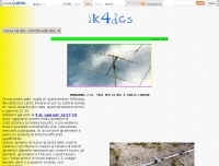 The webpage provides information on a two-element Yagi antenna for 24 Mhz, created by IK4DCS. It includes details on the design and construction of the antenna.
 -
 OZ2OE Technical pages, a 3 element 28 MHz light weight Yagi for 10 meters band
 -
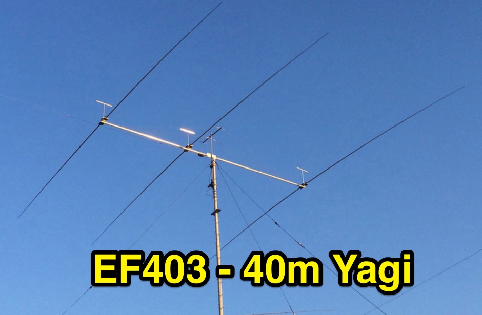 EF403 is a 3 element yagi antenna for the 40 meters band with high gain and F/B Ratio
 -
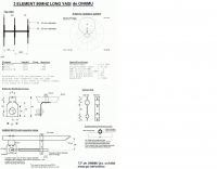 A 3 elements long yagi antenna for 6 meters band by ON6MU
 -
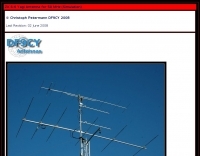
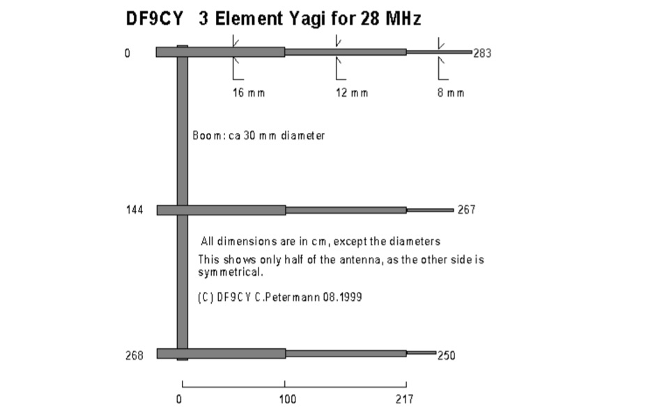 The DF9CY three-element antenna for 28 MHz by Christoph Petermann DF9CY
 -
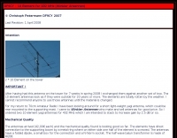
 VHF Optimized Yagi Antenna for the 6-meter band (50 Mhz) by ON6MU
 -
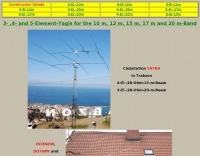
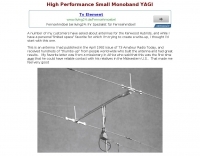
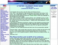 17 Meter 3 element TA33 junior mono band yagi antenna conversion project by K6TC
 -
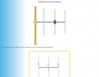
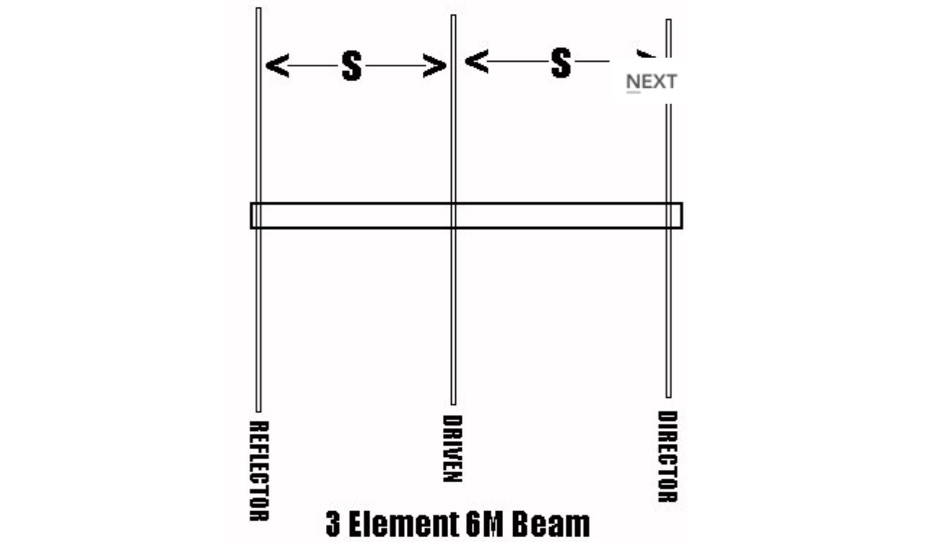 Plans for 3 elements beam antenna and gamma matches
 -
 All these plans use the DK7ZB match
 -
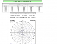
 3 elements VHF Yagi homebrew antenna designed with YAGIMAX 3. Maximum forward GAIN is about 8,17 DBi. This antenna offering an effective radiation power 4 times greater of the transceiver output by SV1BSX
 -
 A 3 element yagi beam for 40 meters band
 -
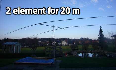
 Pictures and plans of a 4 elements yagi beam antenna for 14 Mhz
 -
 A homebrew project for a 2 meter 4 element yagi beam antenna by 2E0HTS
 -
 Picture and construction details of a 5 element 20 meter monobander
 -
 A 5 elements yagi antenna for 10 meters band project, plane and picture of the EF105A by YU7EF
 -
 U6YRN 6 element yagi antenna for 430-450 Mhz
 -
 6 Elements on 50 MHz / 6 metres
 -
 ON6MU optimized 6/9 element vhf yagui antenna with antenna schematic plan and pictures of homebrewed samples.
 -
 A 7 elements yagi beam monoband antenna for 14 Mhz by VE3GK
 -
 The QM7 antenna is a simple 7 elements Yagi with 3.7 m boom length for the lower 144 MHz SSB/MGM band, in PDF Format
 -
 YU7EF 8 elements yagi antenna for 4 meters band
 -
 Construction details for a 9-element 432 MHz DK7ZB-type Yagi antenna, including EZNEC calculations, dimensions, stacking, and build photos.
 -
 A simple design of a 9 elem. yagi antenna for 2 meters band
 -
 Long yagi antenna for 50 Mhz band
 -
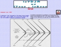 5 elements "vee" log-yagi for 10m band- boom lenght : 4mt. Gain : over 10 dBd , f/b =over 40 db (deep null) f/b= min 20dB for different polarization signals
 -
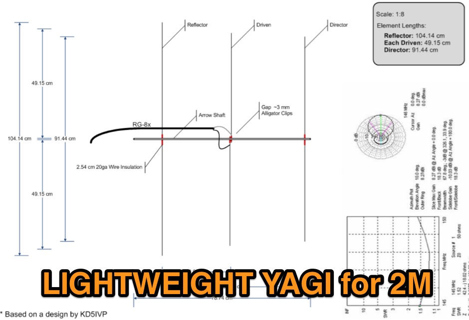
 Build a portable VHF yagi antenna for 2 meters. All you need is two rabbit ear antennas from Radio Shack, two CATV baluns, four feet of 3/4 CPVC pipe with one tee.
 -
 HF Wire Yagi antenna with notes and eznec file on original article of a Portable 3-Band Yagi antenna for 10-15-20 meter band made with wire elements. Include link the original to QST article.
 -
 Simple gain antennas for the beginner, a 2 element HF yagi antenna
 -
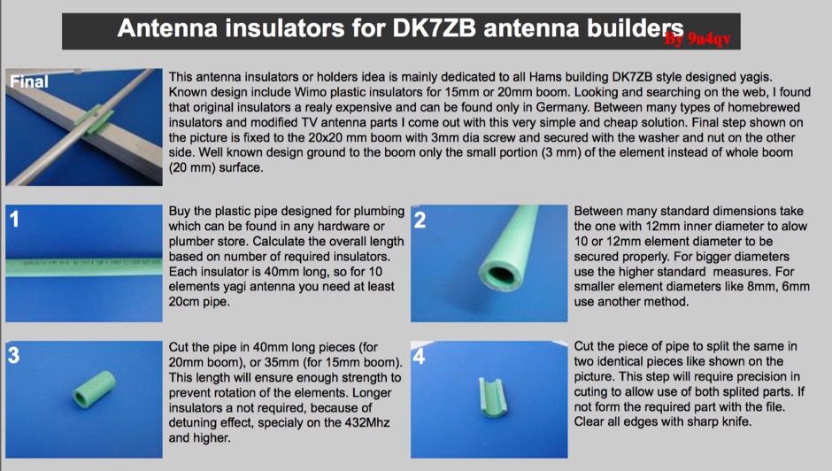 Homebrew antenna insulators for DK7ZB yagi antennas
 -
 by Zaba, OH1ZAA / NN0Y
 -
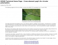 OZ2OE Technical Home Page - Building a circular polarized yagi
 -
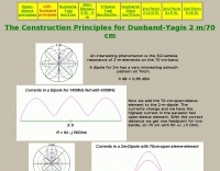 The Construction Principles for Duoband-Yagis 2m/70cm by DK7ZB
 -
 A 4 element addition for 10m to an existing 4 element yagi (ZX antennas)
 -
 10-12-15-17 meter band yagi antenna
 -
 Yagis for homemade with a new match-system, for 6m, 4m, 2m, 70cm and Shortwave
 -
 A 4 yagi beam VHF antenna made with PVC easy to carry in a backpack for portable operations
 -
 5 elements Yagi antenna with an 8.7 db gain
 -
 PA5DD version of the dual band yagi antenna for 50 and 70 Mhz
 -
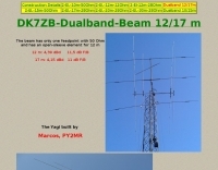 The beam has only one feedpoint with 50 Ohm and has an open-sleeve element for 12 m by DK7ZB
 -
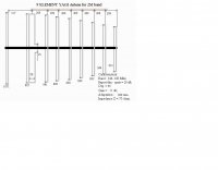
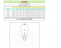 This is a plan for a 10 elements yagi antenna for 50 mhz
 -
 2 element Yagi antanna plan from G3SYC
 -
 A gamma match example
 -
 ON6MU Optimized 10 and 6 and 4 element UHF Yagi Antenna
 -
 VHF Yagi antennas with low Q, extending the boom.
 -
 AB4GX K4EAA Mononband yagi antenna for 20 Meters
 -
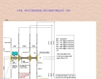 F6CHT plan for a multiband yagi antenna that covers 6 to 30 meters band in french
 -
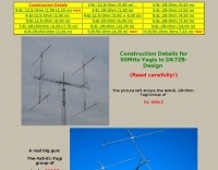 Construction Details for 50MHz-Yagis in DK7ZB-Design
 -
 A Portable 2 element Triband Yagi antenna that can work on 10 15 20 meter band by VE7CA
 -
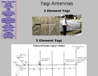 A 3 and 5 element portable yagi antennas for 2 meter band
 -
 The QM7 antenna is a simple 7 elements Yagi with 3.70 m boom length for the lower 144 MHz SSB/MGM band, used it mainly for Sporadic-E and MS contacts. It exhibits a forward gain of 11.35 dBd; i.e. 13.5 dB forward gain over the isotropic radiator, while the F/R is about 12.5 dB
 -
 Article describing how to homebrew a yagi antenna for 50 MHz, includes plans for a four and five elements yagi beam and details how how match impedence with a gamma match
 -
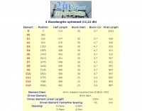
 These yagis and groups were designed with YO7.23 from K6STI and checked with EZNEC from W7EL. With a gain of 14/17/20dBd they have a good relation between gain and mechanical problems.
 -
 Constructing and designing full size, single band stacked yagi antenna arrays
 -
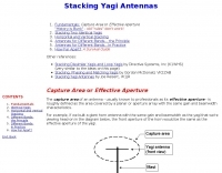 About Stacking yagi antennas by OH1ZAA
 -
 4 Element Cubical Quad, Yagis, LZA Circular Quad, Shrunken Quad , quarter wave, J-Pole, beam mounting , changing polarity
 -
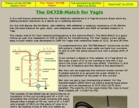 Simple, easy to built match developed in 1995 for Yagis with resistitive loads of 12.5, 18 and 28 Ohm.
 -
 Interesting variant on the 3-element Yagi. Lightweight fiberglass (or similar) tubes supporting a wire structure of elements
 -
 Yagis for 20 15 10 meters band by Nathan A. Miller
 -
 Presents **NW3Z** optimized wideband Yagi antenna designs for 20m, 15m, and 10m bands, originally featured at Dayton 2001. Includes design files.
 -
 A 70cm and 2m 6 elements yagi antenna plan based on the IEEE Transactions on Antennas and Propagation
 -
 The RDF 10 second fold-out Yagi especially for fox hunting. have more fun stuff on this page. PD0G
 -
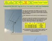 A triband VHF Yagi antenna for 6 m, 4 m and 2 m with one feed-point by DK7ZB
 -
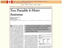 VE7CA reprint an interesting article taken from arrl antenna compendium. Two elegant practical and portable 6-meter gain antennas, a two-element quad and a tree-element Yagi antenna for 50 Mhz-6 meter band
 -
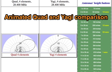 Animated quad and yagi comparison. You can see antennas' characteristics behavior in a vertical plane with changing of the height.
 -
 The W8JK is a famous and effective DX antenna, first built by John Kraus, W8JK, in 1937. A Beam antenna with two parallel dipoles driven with opposite phase, with a close spacing of an eighth of a wavelength.
 -
 F6DED page of a 2 element beam W8LK antenna with pictures and dimensions, in french
 -
 An old project by I1VCF for a 3 element yagi antenna originally designed for 10/15/20 and extended to 24 and 18 Mhz in Italian
 -
 A 3 element yagi antenna for 17 meters
 -
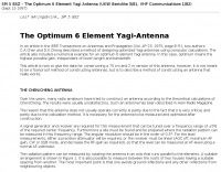
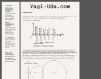 The Yagi-Uda antenna, information on basic design, project and measure of Yagi-Uda antenna, include free repository/sample of beam antenna.
 -
 Antenna dimension, diagram and simulation of the ZX Antennen ZX 6-6 Yagi for VHF UHF by DF9CY
 -
 A homebrew 13 elements yagi antenna for two meters band. These project includes two model of the same antenna with a 6 and 7 meter boom length. Detailed pictures and nec files are available for download
 -
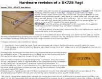
 This Yagi has a constant element-distance of 1,50 m. You must only correct the lengths of the elements for QSY, see table down. For the bands 10 m and 12 m the Yagi is working as a reflector-radiator-Yagi, for 15 m and 17 m as a beam with radiator and director.
 -
 Ultra-lightweight 2m Yagi for SOTA
 -
 A great and efficient monoband VHF portable antenna. The article consist of two version of a 12.5 Ohm 3 elements yagi beam antenna plans for the two meter band, a full sized and a shortened version expecially designed for the SSB and CW on 144 MHz.
 -
 4 elements Yagi antenna for 28 MHz
 -
 A 5 elements homemade DK7ZB yagi antenna for 4 meters band based on a 50MHz TONNA
 -
 YT1VP Yagi antenna for 6 meters
 -
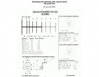
 This is a plan for an optimized element UHF Yagi Antenna for UHF Bands featuring a 9dBd forward gain, a 13 dB front-back ratio, and a bandwith of 10 MHz on the 430-440MHz range.
 -
 An article describing how to homebew a VHF 4 elements Yagi antenna.
 -
 This article describes the phases for the construction of a Yagi antenna. The calculations of the parameters are made using 4NEC2 software. This type of antenna is used for transmissions and receptions of electromagnetic waves. The project shown here refers to the frequency of 433.92 MHz.
 -
 This DIY guide details constructing a 5-element Yagi antenna for VHF frequencies. Yagi antennas offer directional signal transmission/reception compared to omnidirectional ones. The guide covers material selection (aluminum, screws, etc.), design using software or formulas, and step-by-step assembly including cutting elements, drilling holes, and attaching the coaxial cable. While calculations are provided for a 146 MHz design, adjustments are necessary for different frequencies. Safety precautions and potential result variations are emphasized.
 -
 A project for a home made 5 element yagi-uda antenna for 2 meters, covering 144-148 MHz band by N1BMX
 -
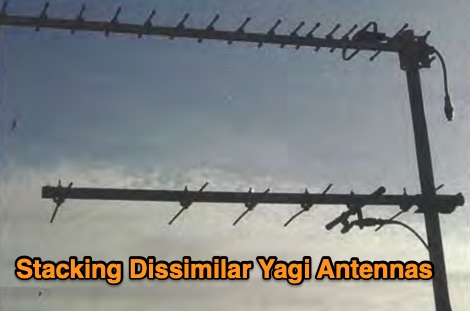 In this article the author provides some guidelines on how to solve a common problem when stacking different types of yagi antennas on the same mast, limiting the effects on gain and radiation pattern of both antennas
 -
 This project introduces the Loggi, a hybrid antenna merging the wide frequency coverage of log-periodic dipole arrays (LPDA) with the high gain and front-to-back ratio (F/B) of Yagi antennas. Traditional LPDAs span broad frequencies with moderate gain and low VSWR, while Yagis provide high gain and F/B over narrow bands. By analyzing high-Tau LPDA designs, it was found they could nearly match the gain of VHF/UHF Yagis while maintaining excellent patterns, F/B, and front-to-rear ratios (F/R). Optimizing specific elements for target frequencies (e.g., 144.1 MHz) led to the Loggi, which uniquely features all driven elements without passive directors or reflectors. This design effectively functions as a narrowband optimized LPDA, with front elements acting like Yagi directors and rear elements like Yagi reflectors, thus enhancing gain and directional characteristics while retaining broad frequency versatility.
 -
 A collection of 450 MHz Cheap Yagis that have proven great portable operations, back-packing and transmitter hunts, and are something inexpensive you can throw up in the attic for that weak repeater
 -
 Article on 50 Mhz Yagi Antennas stacking by OH1ZAA/NN0Y
 -
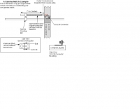
 A cost-effective alternative to the Optibeam OB10-3W, a high-performance but expensive tri-band Yagi antenna for the 20, 17, and 15-meter bands. The original Optibeam, featuring three full-size elements on each band, delivers strong forward gain and front-to-back ratio but comes with a high price tag. To address this, a custom design was developed, offering similar performance at a fraction of the cost. Using accessible materials and a simple 1:1 current balun, the homemade version proved highly effective, making it a practical solution.
 -
 A ten element ultra-lightweight yagi beam antenna for 144 MHz based on YU7EF design concept
 -
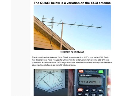 Basic priciples of Yagi antennas and its variations like Quagi antennas, Quad antennas includes pictures, drawings and online calculators by KN9B
 -
 A 2 elements yagi beam for 12 meters band with liear load
Frequently Asked Questions
What is a Yagi antenna and where does the name come from?
A Yagi antenna, more formally known as a Yagi-Uda antenna, is a directional antenna commonly used at HF, VHF, and UHF frequencies. It consists of a driven element (usually a dipole or folded dipole), a reflector, and one or more directors. The name comes from its inventors, Shintaro Uda and Hidetsugu Yagi, who developed it in Japan in 1926. While Uda did most of the experimental work, professor Yagi published the first English-language article on the antenna, leading to its common name.
For which frequency bands are Yagi antennas commonly used in amateur radio?
Yagi antennas are widely used across various amateur radio frequency bands, particularly where directional gain is beneficial. They are very popular for VHF (e.g., 2 meters, 6 meters) and UHF (e.g., 70 cm) operations, including satellite communications and weak-signal work. On HF bands, Yagis are common for 10, 15, and 20 meters, where their gain and directivity are crucial for long-distance DXing. While technically possible, building efficient multi-element Yagis for lower HF bands (like 40 or 80 meters) becomes physically very large and challenging due to the longer wavelengths.
What is the importance of impedance matching for a Yagi antenna?
Impedance matching is crucial for a Yagi antenna to ensure maximum power transfer from the transceiver to the antenna and minimize reflected power (SWR). The driven element of a Yagi typically has a feedpoint impedance that may not be a perfect match for standard coaxial cable (e.g., 50 ohms). Without proper matching, a significant portion of the transmitted power can be reflected back to the transmitter, leading to reduced efficiency, potential damage to the radio's final amplifier, and poor signal quality. Common matching techniques include using a gamma match, beta match, or a balun with an appropriate transformation ratio.
What factors influence the gain and beamwidth of a Yagi antenna?
The gain and beamwidth of a Yagi antenna are primarily influenced by the number of elements, their spacing, and their lengths. Generally, increasing the number of directors adds more gain and narrows the beamwidth, making the antenna more directional. The spacing between elements is critical; optimal spacing maximizes forward gain and minimizes side lobes. Element lengths are tuned for the desired operating frequency. Longer booms typically allow for more elements and thus higher gain, but also increase the antenna's physical size and wind loading.
What are the advantages of using a Yagi antenna compared to an omnidirectional antenna?
The primary advantage of a Yagi antenna over an omnidirectional antenna is its significant directional gain. This means it can concentrate more of the transmitted power in a specific direction, leading to a stronger signal at the receiving end, or conversely, it can receive weaker signals from that direction more effectively. This directivity also provides excellent rejection of signals and noise coming from other directions, improving signal-to-noise ratio. Omnidirectional antennas, while simpler, spread their power in all directions, resulting in lower signal strength in any single direction.
Are Yagi antennas used in applications other than amateur radio?
Yes, Yagi antennas are widely used in many applications beyond amateur radio due to their excellent directional gain and relatively simple construction. Common uses include terrestrial television reception (especially for distant signals), point-to-point wireless data links, cellular base stations, satellite communication ground stations, and even some radar systems. Their ability to focus RF energy in a specific direction makes them ideal for situations where maximizing signal strength or minimizing interference from other directions is crucial.
What are the main components of a typical Yagi antenna?
A typical Yagi antenna consists of several key components mounted on a boom. These include the driven element, which is the part directly connected to the transceiver's feedline and is usually a dipole or folded dipole. Behind the driven element is the reflector, a slightly longer parasitic element that helps push the signal forward. In front of the driven element are one or more directors, which are slightly shorter parasitic elements that further focus the radiation pattern. All these elements are mounted on a non-conductive or conductive boom, which provides structural support and maintains the correct spacing between elements.
How does a Yagi antenna work to achieve its directional properties?
A Yagi antenna achieves its directionality through the interaction of its parasitic elements (reflector and directors) with the driven element. The reflector, typically slightly longer than the driven element, is placed behind it and reflects radio waves forward. The directors, typically slightly shorter than the driven element, are placed in front and help to focus and steer the radio waves in the desired direction. This arrangement creates constructive interference in the forward direction and destructive interference in other directions, resulting in significant gain and directivity.